Texas Instruments
www.chez.com/loverdeContentsTI Map/SearchFeedbackTI
Educational ResourcesProduct InformationAccessory StoreCustomer Support and ServicesFree DownloadsInternational Information

-----

Linear Circuit Analysis:
  • Charge and Current
  • Work, Power, Voltage, and
          Resistance
  • Kirchoff's Laws
  • Y Delta, Node, and Loop
  • Circuits with Operational
         Amplifiers
  • Network Theorems
  • Analysis of Diode Circuits
  • Capacitance and Inductance
  • First-Order Transient Circuits
  • AC Steady State Analysis
  • Steady State Power
  • The Power Factor
    Introduction

    adv.92g
    circuits.92g
    delta2yt.92g

  • Linear Circuit Analysis:
    Steady State Power

    ------------

    Determine the total average power absorbed or supplied by each element in the network.
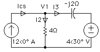
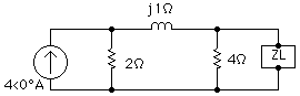
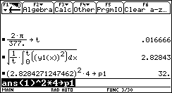
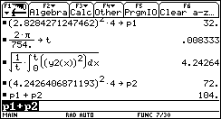
    Irwin. page 465 drill 10.3

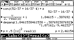
    We know how to find power with non-complex sources and elements. When complex sources and elements are involved the formulas for power are enhanced to compensate. Capacitors and inductors are referred to as lossless elements. Therefore, we say that they absorb 
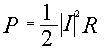
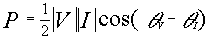
no power. For complex sources, the formula that relates power to current and voltage is:


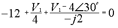
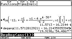
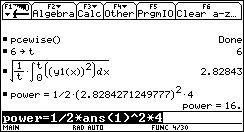
    Given the voltage and a resistive element, the power absorbed by the resistor is given by the relationship:


    Given the current and a resistive element, the power absorbed by the resistor is given by the relationship:

    Since these are pretty important formulas, let's add them to the text file for safe keeping.
    To find the power for each element we need to find all the voltages and currents. At the top of the circuit we can find the voltage by writing a single KCL equation as the sum of all the currents leaving the node equals zero.

    • Call the cZeros function on the TI-92 by pressing [F2] [A] [3]. Enter the KCL equation assumed to be equal to zero. Store this to the variable v1.
      Note. Since the zeros and cZeros functions return their answers in the form of a list, the extra [1] parameter was used to extract the first (and in this case the only) element from the list before storing the complex number to v1.
    • Press [2nd] [CUSTOM] to call the custom menu. Use the DegAng function by pressing [F3] [ENTER] [ENTER].

    Now that we know the voltage we can find the power consumed by the resistor and the current source.

    • Following the format of the equation in the text editor involving voltage and resistance, we find the power delivered to the resistor.
    • Following the format of the equation in the text editor involving voltage and current, we find the power provided from the current source.
    • The current through the branch I2 is equal to the voltage at the top of I2 (v1) divided by the resistance. Knowing that we can find this value we can easily solve for the current I3 by KCL.
      I3 = ICS - I2
    • Store this answer in the variable i3.
    Note: Since the arrows on our diagram show the current entering the negative terminal of the current source we should say that the current source absorbs -69.4277 Watts.
    • Knowing the current I3 and the voltage provided by the voltage source, we can find the power absorbed by the voltage source. For this we use the formula for power involving complex current and complex voltage.
    Note: Since the arrows on our diagram show the current entering the positive terminal of the voltage source we say that the voltage source absorbs +19.8277 Watts.


    Given the circuit, find the value for ZL for maximum average power transfer. Also find the value of the maximum average power transfer delivered to the load.
    Irwin. page 468 example 10.6


    • We find the open circuit voltage by multiplying the current through the 4 ohm resistor by the 4 ohm resistor. This value is stored to the variable v for later calculation.
    • With the custom menu in place, press [F3] [ENTER] [ENTER] to change the complex number to a magnitude and an angle.
    The Thévenin equivalent is found by looking at the circuit from the output terminals with the sources turned off. No current flows through a turned off current source (Open).
    • Using the parallel function, we find the Thévenin impedance.
    • The complex conjugate of the Thévenin impedance gives us the impedance for maximum average power transfer. Store this value in the variable z for later calculations.
    • With the impedance given as before, we can calculate the current through the load. The current is calculated as the open circuit voltage divided by the total impedance (Zth + ZL). Since Zth = conj(ZL), the total impedance can be written as 2 * real(z). Store this value to the variable i for later calculations.
    • With the custom menu in place, press [F3] [ENTER] [ENTER] to change the complex number to a magnitude and an angle.
    • Now that we know the load impedance and the current through the load, we can use the formula given earlier that relates these two items to power.
    Given the waveform of the current flowing through a 4 ohm resistor. Compute the average power delivered to that resistor.
    Irwin. page 475 drill 10.8
    This waveform represents a constantly repeating wave. This portion was drawn using the PceWise program found in the custom menu at [F2] [1].
    From negative infinity to 2 graph the line 2.
    From 2 to 4 graph the line 4.
    From 4 to 8 graph the line 2.
    From 8 to 10 graph the line 4.
    From 10 to infinity graph the line 2.
    The window variables are set as shown.
    For any type of voltage of current that can be graphed, store the equation in the y(x) editor of the TI-92. Then the RMS value can be found by following the equation:

    Where T is the period of the wave. For sinusoidal functions:

    These two formulas are added to the Text editor with a command line for easy use.
    By looking at the graph of the current, we can see that it repeats every six seconds. The PceWisc program has already stored the equation for the graph in the y(x) editor as y1(x).
    • Store 6 as the value of the period to the variable t.
    • Enter the text editor by pressing [APPS] [9] [ENTER], place the cursor on the formula for RMS value and press [F4] (Execute).
    • After the problem has been evaluated, press [2nd] [QUIT] to return to the home screen.
    • The value on the home screen is the RMS value for the current. To find the RMS value for the power delivered to the resistor delivered to a 4 ohm resistor, we need to apply the P=I2R formula
    Note: There are no complex numbers or phasors involved in this calculation. Therefore, we use the DC formula for power in terms of current and resistance.


    The current i(t) is flowing through a 4 ohm resistor. Determine the power absorbed by the resistor if:
    i(t)=4sin(377t-30o)+6cos(377t-45o)A

    Irwin. page 475 drill 10.10

    Since the frequencies vary between the cosine and sine function, this problem needs to be done in two parts by way of superposition.

    • Store the first part of the equation in the y(x) editor as y1(x).
    • Store the second part of the equation in the y(x) editor as y2(x).

    • Omega for the first part of this function is 377. Store the value of 2*Pi/377 to the variable t (Period).
    • Press [APPS] [9] [ENTER] to go to the text editor. With the cursor on the line with the formula for RMS values, press [F4] (Execute).
    • After the equation has been evaluated, press [2nd] [QUIT] to return to the home screen.
    • The value on the home screen is the RMS value for the current. To find the RMS value for the power delivered to the 4 ohm resistor from the first part of the current source, we need to apply the P=I2R formula to find its contribution to the power. Store this in the variable named p1.
    Note: There are no complex numbers or phasors involved in this calculation. Therefore, we use the DC formula for power in terms of current and resistance.
    • Omega for the second part of this function is 754. Store the value of 2*Pi/754. to the variable t (Period).
    • Scroll up to the equation for RMS value. Press [ENTER] to move it to the entry line. Change y1(x) to y2(x) and press [ENTER].
    • The value on the home screen is the RMS value for the current. To find the RMS value for the power delivered to the 4 ohm resistor from the second part of the current source, we need to apply the P=I2R formula to find its contribution to the power. Store this in the variable named p2.
    • Add p1 and p2 together to find the total power delivered to the resistor.
    • Graph of y1(x), y2(x) and y3(x)=y1(x)+y2(x). xMax is set to 8*Pi/754 to show how the frequency of the current repeats.


    Retour site Christian LoverdeContentsTI Map/SearchFeedbackTI

    (c) Copyright 1998 Texas Instruments Incorporated. All rights reserved.
    Trademarks