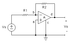
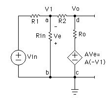
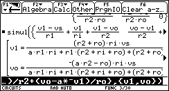
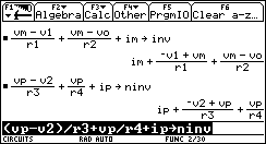
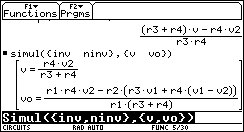
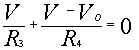
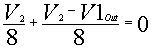
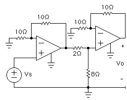
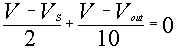
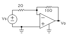
The KCL node equation at the inverting terminal is:
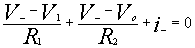
This equation is written as the sum of all
the currents leaving the node equals zero.
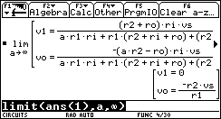
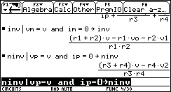
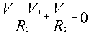
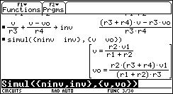
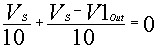
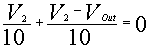
At the non inverting terminal the KCL node equation yields:
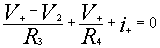
This equation is written as the sum of all
the currents leaving the node equals zero.
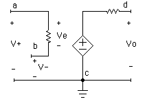
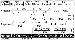
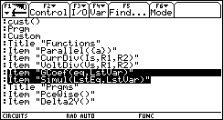
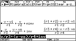
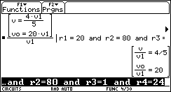
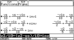
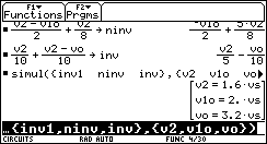
On the TI-92,
V+is written as vp, V- is written as
vm, i+ is written as ip, and
i- is written as im. |