Texas Instruments
www.chez.com/loverdeContentsTI Map/SearchFeedbackTI
Educational ResourcesProduct InformationAccessory StoreCustomer Support and ServicesFree DownloadsInternational Information

-----

Linear Circuit Analysis:
  • Charge and Current
  • Work, Power, Voltage, and
          Resistance
  • Kirchoff's Laws
  • Y Delta, Node, and Loop
  • Circuits with Operational
         Amplifiers
  • Network Theorems
  • Analysis of Diode Circuits
  • Capacitance and Inductance
  • First-Order Transient Circuits
  • AC Steady State Analysis
  • Steady State Power
  • The Power Factor
    Introduction

    adv.92g
    circuits.92g
    delta2yt.92g

  • Linear Circuit Analysis:
    AC Steady-State Analysis

    ------------

    Convert the time functions
    v(t) = 24 cos(377t-45o)V and
    i(t) = 12 sin(377t + 120o)A
    to phasors.

    Irwin. page 405 example 9.6

    Phasors are represented in the frequency domain by a complex number written as a magnitude and an angle in degrees. This is possible because the frequency of an input signal is not changed within a circuit. Phasors are written from time functions following the formulas.


    Time Domain Frequency Domain
    • For Safe keeping, let's add these conversions to the text file.
    On the TI-92, complex numbers in the form of a magnitude and an angle are expressed in notation. Where r is the magnitude, i is the imaginary operator [2nd] [i] on the TI-92 keyboard, and theta is the angle in radians. LEAVE THE CALCULATOR IN RADIAN MODE! To work around this we can force degrees by using the degree operator [2nd] [D]. In order to get the calculator to return an answer that we recognize, we can use a function that is a part of the ThevNor program discussed on the Network Theorems page. The function is named DegAng. Degang takes a complex number for an input parameter and returns a string in the recognizable form of a magnitude and an angle. Since we will be using this function a lot, lets put it in the custom menu for easy access.


    Find the impedance of a 20-mH inductor when a sinusoidal voltage source with a frequency of 60 Hz is applied.
    Irwin. page 413 example 9.11

    The impedance for an inductor is found by applying the formula:


    This will make a handy function
    • From the home screen press [APPS] [7] [3] to open a new program editing session.
    • Select function as the type, enter the variable name as ZL, and press [ENTER] twice.
    • Use obscure variables to avoid circular definition errors.
    The formula will be added to the text file and added to the custom menu as well.
    • Using the function that we just wrote, pass in the parameters.
    • L equals the inductance.
    • omega equals 2 * Pi * frequency.
    Find the impedance of a 100-microF capacitor when a sinusoidal voltage source with a frequency of 50 Hz is applied.
    Irwin. page 411 example 9.10

    The impedance for a capacitor is found by applying the formula:


    For completeness let's make this a function as well
    • From the home screen press [APPS] [7] [3] to open a new program editing session.
    • Select function as the type, enter the variable name as ZCap, and press [ENTER] twice.
    • Use obscure variables to avoid circular definition errors.
    The formula will be added to the text file and added to the custom menu as well.
    • Using the function that we just wrote, pass in the parameters.
    • C equals the capacitance.
    • omega equals 2 * Pi * frequency.
    Find and graph all of the voltages and currents of the circuit.
    Irwin. page 426 example 9.17

    We will solve this entire circuit using nothing more than ohm's law, voltage division and the parallel function. The only difference between this circuit and one containing only resistors, is that we get to use complex numbers.

    • Using the parallel function we can change this circuit into a simple circuit containing only one loop. We combine the 8 ohm resistor and the -j4 ohm capacitor with the j6 ohm inductor.

    We are then left with the resulting circuit.

    • I1 can now be found easily using Ohm's law. Store in the variable i1 for graphing later.
    • With the custom menu in place press [F3] and [ENTER] twice to use the DegAng function to convert the complex number to phasor form.
    • V1 can now be found using the VoltDiv function. Store the answer in the variable v1 for graphing later.
    • With the custom menu in place press [F3] and [ENTER] twice to use the DegAng function to convert the complex number to phasor form.
    • Knowing the voltage at V1, I2 can now be found using the Ohm's law. Store the answer in the variable i2 for graphing later.
    • With the custom menu in place press [F3] and [ENTER] twice to use the DegAng function to convert the complex number to phasor form.
    • Knowing the voltage at V1, I3 can now be found using the Ohm's law. Store the answer in the variable i3 for graphing later.
    • With the custom menu in place press [F3] and [ENTER] twice to use the DegAng function to convert the complex number to phasor form.
    • Knowing the current through I3, V2 can now be found using the Ohm's law. Store the answer in the variable v2 for graphing later.
    • With the custom menu in place press [F3] and [ENTER] twice to use the DegAng function to convert the complex number to phasor form.
    Now that we know all of the voltages and currents, all we have to do is graph them. Even though we refer to these as being in phasor form, they are really the same as complex numbers. I have written a program named VecGraph for graphing complex numbers as a magnitude and an angle that is available in circuits.92g. The input parameter for this program is a list of complex numbers. For easy access, this program has been placed in the custom tool menu under Prgms. Since we stored the currents under their variable names, we can enter them as the list.
    The graph shows which currents are leading and lagging. Also this graph is an example of how KCL is still applicable even in complex circuits. At the node V1: I1 = I2 + I3 Try it with the program.
    The voltages can be graphed the same way. From the home screen:
    • Select the VecGraph program from the custom menu.
    • Enter {v1,v2,24e^(i60o)} as the list of complex numbers.
    • Press [ENTER].
    The graph shows which voltages are leading and lagging. Also this graph is an example of how KVL is still applicable even in complex circuits. Around the outside loop: Vs = V1 + V2 Try it with the program.


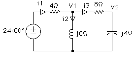
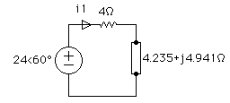
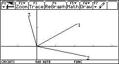
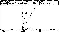
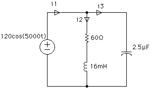
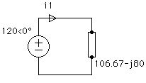
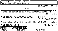
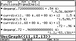
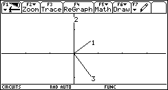
    Find and graph all the currents of the circuit.
    Irwin. page 446 prob 9.28

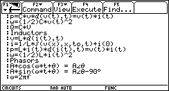
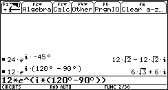
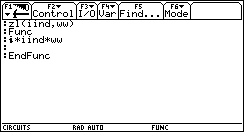
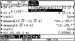
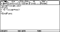
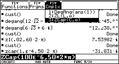
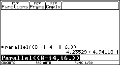
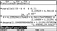
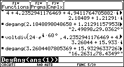
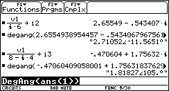
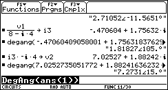
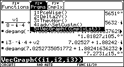
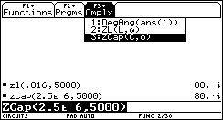
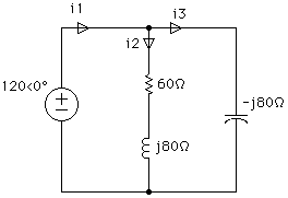
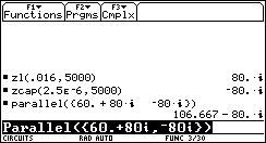
    The first step on this type of problem is to transform the voltage to phasor form and find the complex impedances of the elements within the circuit. The voltage source can be transformed by inspection as having a magnitude of 120 at an angle of 0o. The value of omega (2*Pi*f) from the source is 5000.


    • Use the ZL(L,w) function to find the impedance of the inductor with 16E-3 as the value of L and 5000 as the value of w.
    • Use the ZCap(L,w) function to find the impedance of the capacitor with 2.5E-6 as the value of C and 5000 as the value of w.
    Now the circuit can be redrawn with the voltage source in phasor form and the impedances in complex form.
    • Using the parallel function we can transform this circuit into a circuit with one voltage source and one complex impedance.
    • Using Ohm's law, calculate the current for I1. Store this to the variable i1 for graphing later.
    • With the custom menu in place press [F3] and [ENTER] twice to use the DegAng function to convert the complex number to phasor form.
    • Using the CurrDiv function and the complex impedances, find the current I2 through the capacitor. Store this to the variable i2 for graphing later.
    • With the custom menu in place press [F3] and [ENTER] twice to use the DegAng function to convert the complex number to phasor form.
    • Using the CurrDiv function and the complex impedances, find the current I3 through the capacitor. Store this to the variable i3 for graphing later.
    • With the custom menu in place press [F3] and [ENTER] twice to use the DegAng function to convert the complex number to phasor form.
    • Use the VecGraph program to graph the currents.
    The graph of the currents show which currents are leading and lagging. Also notice that the current through I2 is purely imaginary. Once again the graph shows how KCL still holds true even for complex circuits.


    Retour Site Christian LoverdeContentsTI Map/SearchFeedbackTI

    (c) Copyright 1998 Texas Instruments Incorporated. All rights reserved.
    Trademarks